
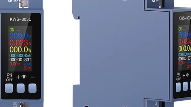
I found this switch on Aliexpress. It’s quite interesting, but it has lack of documentation.
All technical details also available at github.
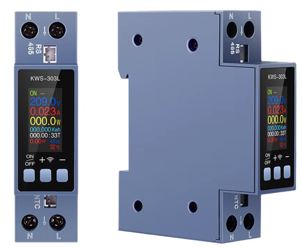
It has following features:
- Frequency meter
- Voltage meter
- Consumed energy meter
- Current meter
- Temperature meter (via thermal couple in NTC connector)
- RS-485 connectivity (modbus) connector
- Active power meter
- Power factor meter
- On/Off switch
- Over/Under voltage protection
- Current Limit
- Max current 40A
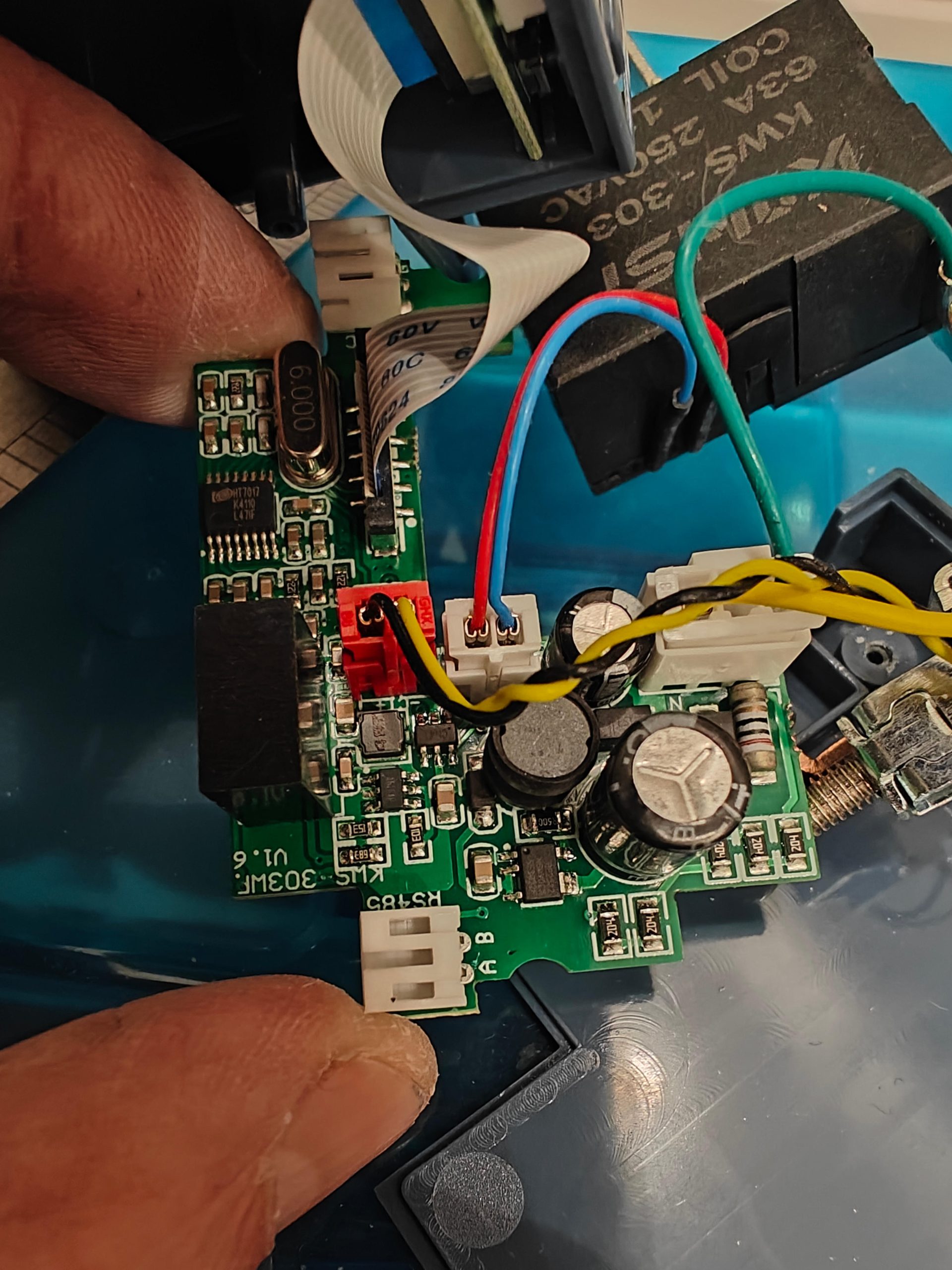
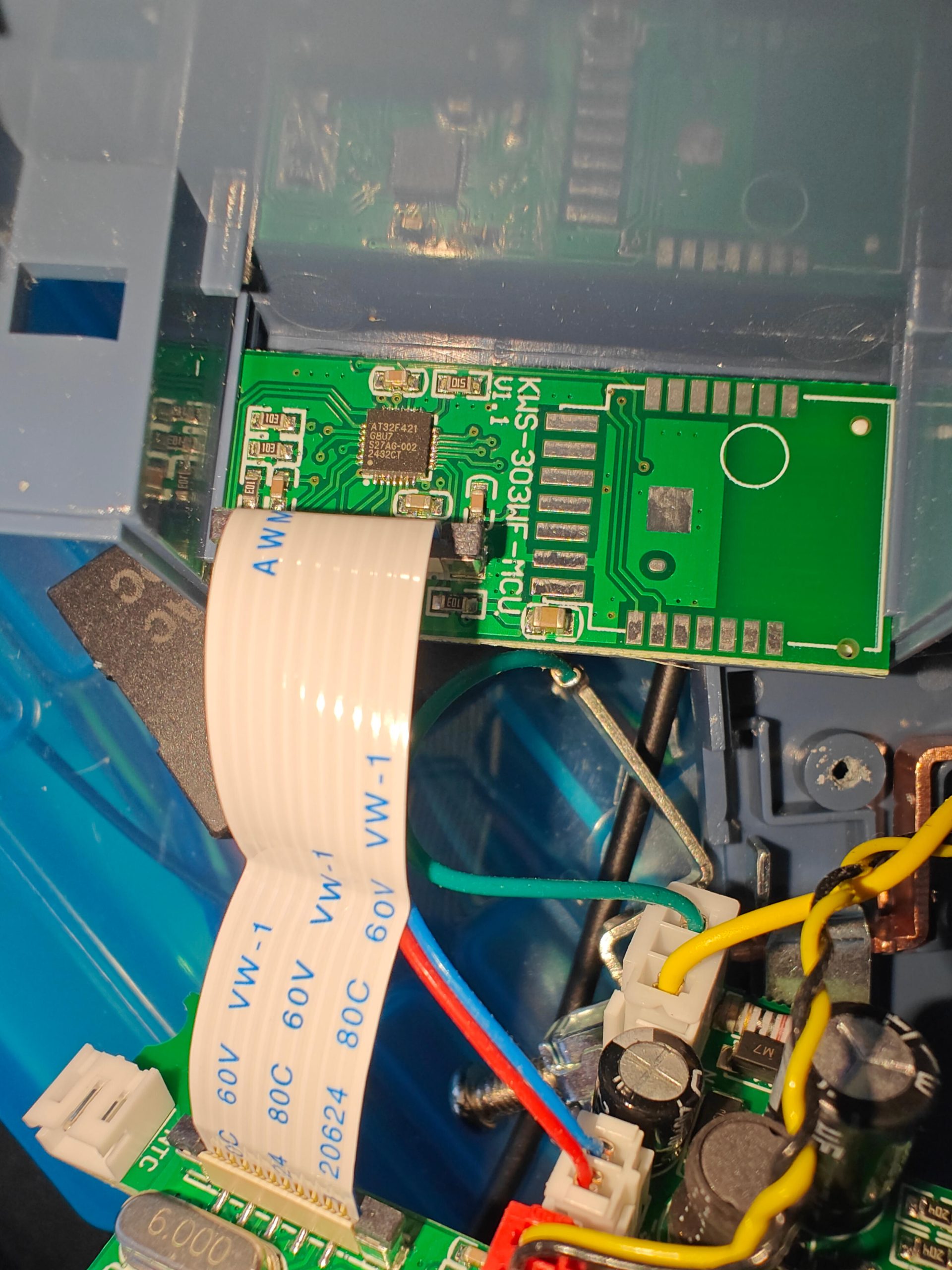
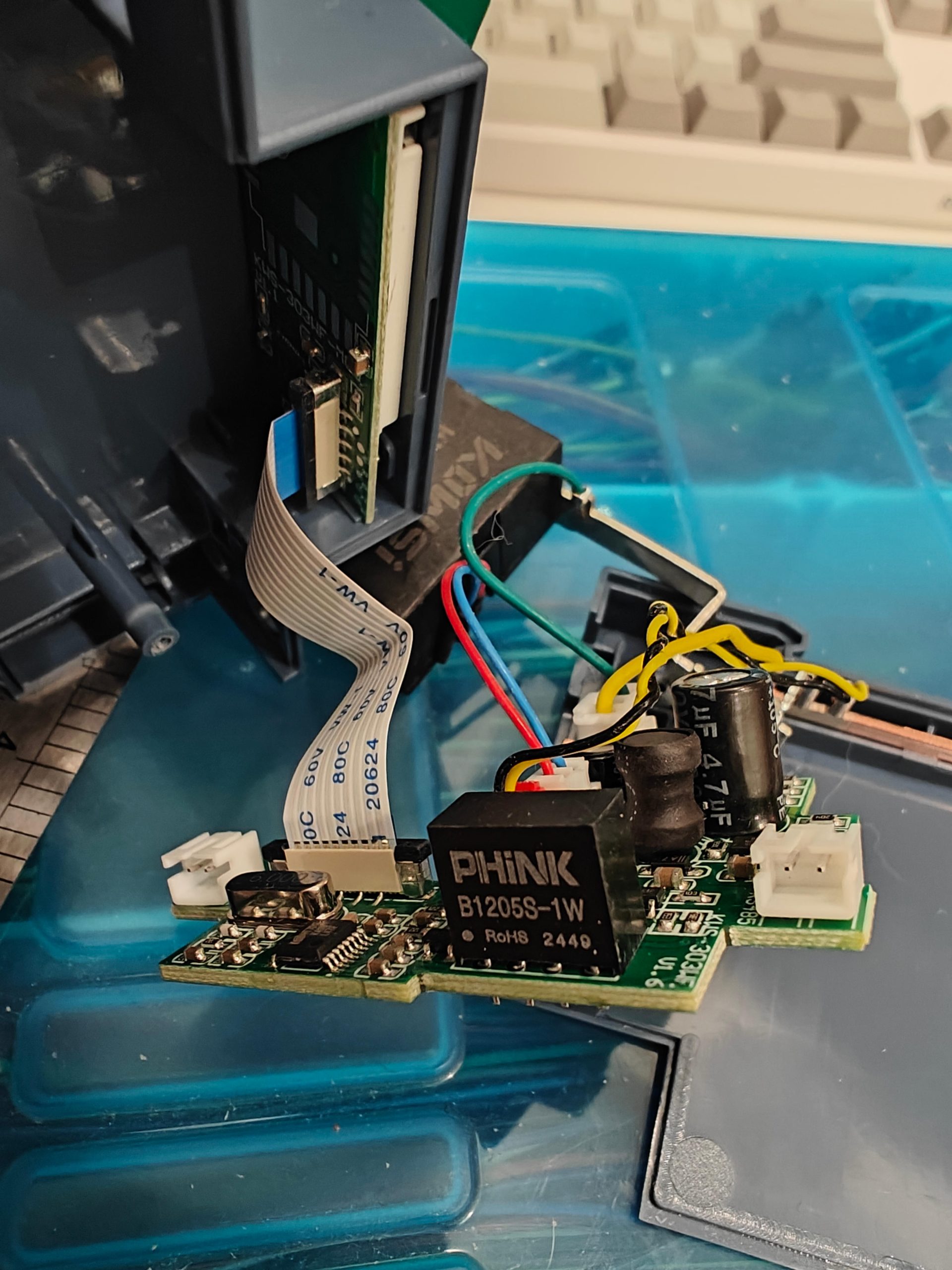
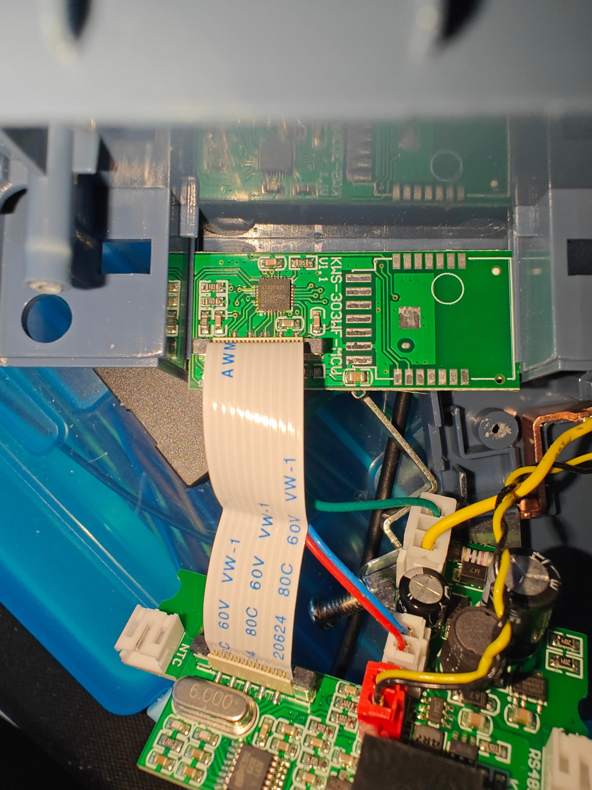
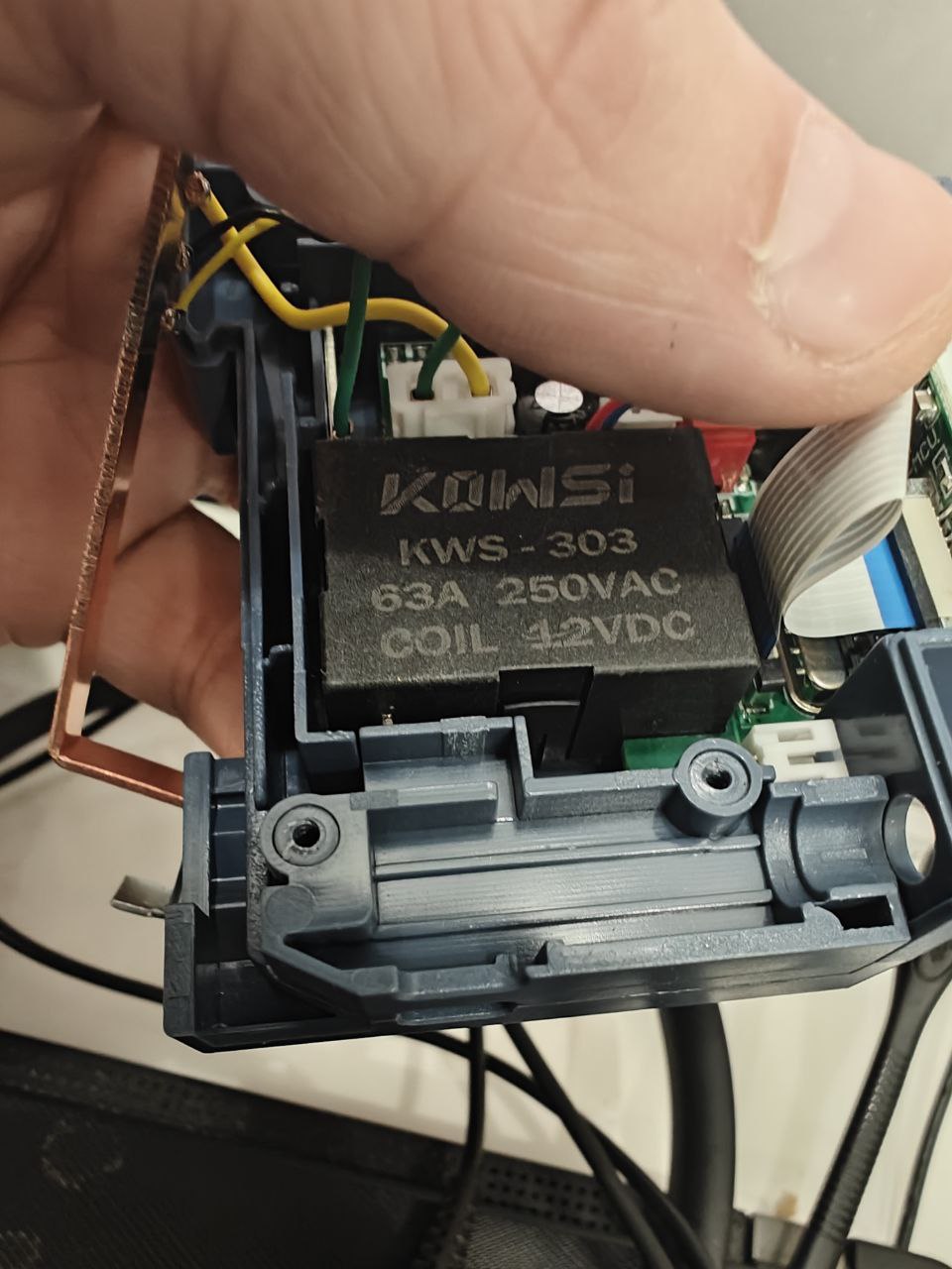
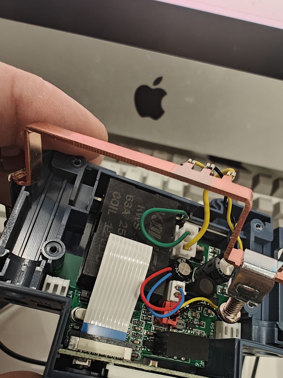
Inside I found quite accurate soldering, thick busbars and AT32F421 32-bit ARM Cortext-M4 MCU.
And there is no any description how to communication with RS-485. Even seller don’t know how to use it. In the settings menu of this device I’v assigned modbus address 2 and start testing.
I suspected that it should has a number of holing registers and to identify the list of registers I wrote simple python script, that just scan all registers from device:
from pymodbus import FramerType
from pymodbus.client import ModbusSerialClient

client = ModbusSerialClient(port="/dev/tty.usbserial-A5069RR4", baudrate=9600, parity='E',
        stopbits=1, timeout=0.1, retries=1, framer=FramerType.RTU)
client.connect()


for i in range(1,100):
  try:
    rr = client.read_holding_registers(i, count=1, slave=2)
    v = client.convert_from_registers(rr.registers, word_order='big', data_type=client.DATATYPE.INT16)
    print("%d | %d" % (i, v))

  except Exception as e:
    print(">>ERROR: %s" % (str(e)))
    pass

client.close()
But before I had to found correct baud rates, stop bits and parity. In reality most of the cheap devices use 9600 as baud rate. So there were no many combination I had to check …
So the configuration is following:
| Property | Value |
|---|---|
| baud rate | 9600 |
| parity | even |
| stop bits | 1 |
| A | red wire from RS 485 connector |
| B | black wire from RS 485 connector |
Here the list of holding registers I found:
| Register | Description | Example | Gain |
|---|---|---|---|
| 1 | Rated voltage (V)(220V) | 220V(Fixed) => 22000 | 100 |
| 2 | Rated current (A) (40A) | 40A(Fixed) => 4000 | 100 |
| 14 | Active Voltage (V) | 229.6 => 22960 | 100 |
| 18 | Active Amperage (A) | 0.012A => 12 | 1000 |
| 26 | Active Power (W) | 3.12W=> 312 | 100 |
| 34 | ?? | ||
| 42 | ?? | ||
| 48 | Power Factor | 0.99 =>990 | 1000 |
| 51 | Active Frequency (Hz) | 50Hz => 5000 | 100 |
| 55 | Consumed Energy (kWh) | 5.5kWh => 5500 | 1000 |
| 60 | Active Temperature (Co) | 25 | 1 |
| 61 | Timing (minutes) | 100 => 100 | 1 |
| 63 | Switch on relay / Switch off relay | On/Off => 1 / 0 | – |
| 64 | Over Voltage Limit (V) | 250V => 2500 | 10 |
| 65 | Under Voltage Limit (V) | 85V => 850 | 10 |
| 66 | Over Amperage Limit (A) | 26A => 260 | 10 |
| 67 | Over Power Limit (W) | 11W => 110 | 10 |
| 71 | Back Light time (minutes) | 6 | 1 |
| 72 | Over Temperature Limit (Co) | 51 => 51 | 1 |
| 74 | Over Energy Limit (kWh) | 12kWh=>1200 | 100 |
| 81 | Screen Rotation | Normal/Rotated => 1/0 | – |
| 82 | Black Light % | 80 | 1 |
PS
Found official documentation on chinese
Hello Alexey,
You did already a great job !
I don’t see a register to control the integrated switch (on/off) by Modbus protocol.
That should also be possible, no ?
Did you find it ?
I would like to control the switch via a connected Arduino with RS485 module.
PS :” Over Energy Limit (Kw)” should be in kWh ( WhatHours, as it is Energy)
Hi, Bart!
Thank you for your feedback. Fixed description.
The register 63 control switch On/Off (1/0) correspondingly.
So you can connect and control it to Arduino via Serial and Modbus library.
I’m using the same approach, but only for ESP32-C6
Hey, Just wanted to say nice work and big thankyou! This has saved me alot of time and I would not have bought this device if not for finding this page. They should be paying you xD
You are welcome, Doug!
Hey, thanks for sharing this! I’ve just received the device and will have a play with it over the weekend. What do you think about the claimed 40A current capability? There’s nothing on the device or in the manual (there wasn’t one lol!) showing any diagrams or specifications. I’d be quite wary of making contact under load.
Hi, Pawel
Added last 2 images for busbar and relay.
Checked it under 16A and it works fine, but not sure about 40A
In this switch there are 4 possible weeknesses:
* PCB – using thick copper layer and looks fine.
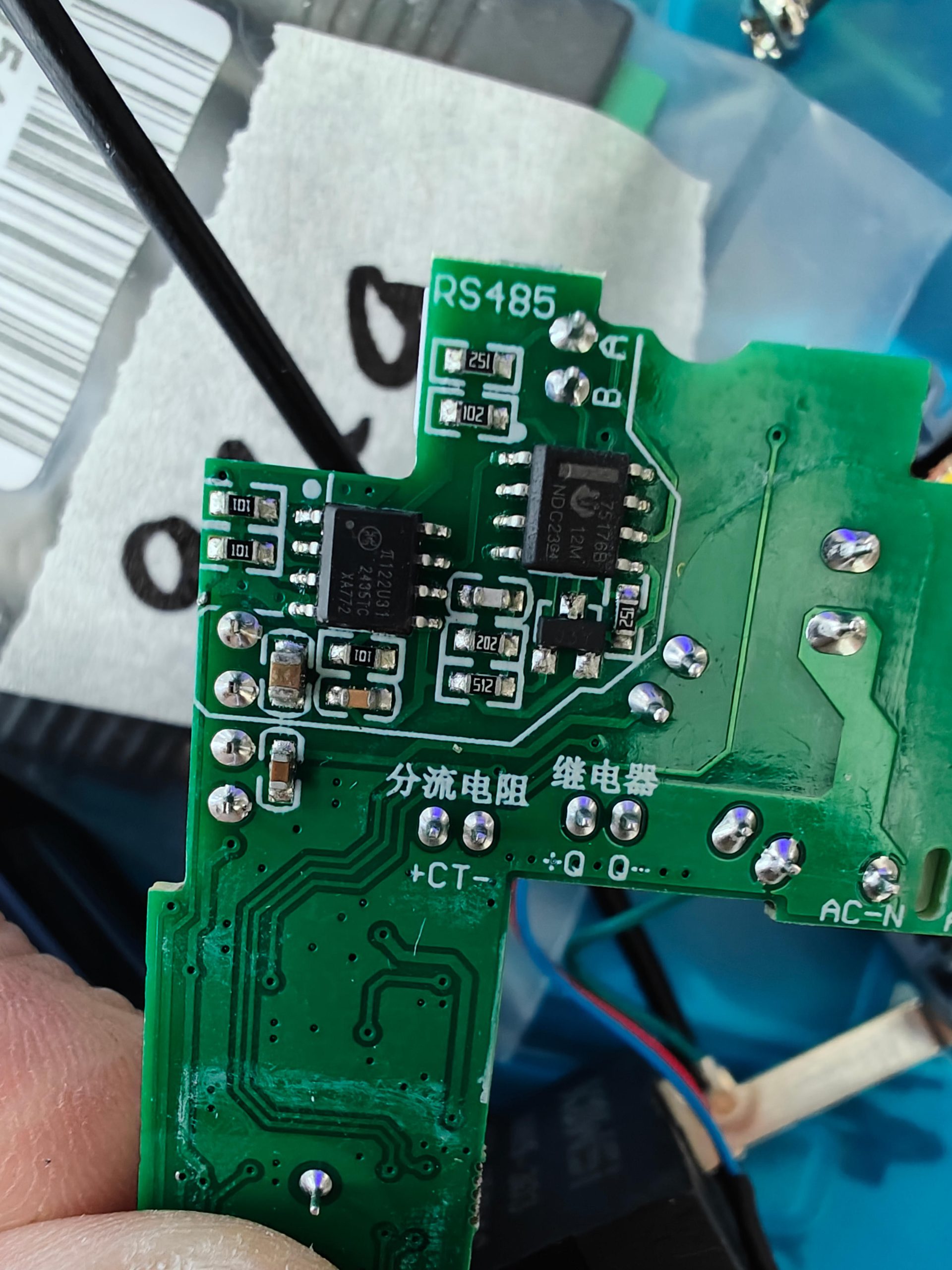
* Busbar – busbar has about 5mm*1.2mm ~ 6mm2 сross-section and looks like copper (at least needle file leaves notches of the same color). Look at last image
And for copper 6mm2 max current > 40A. So it’s looks OK
* Relay – rated current 63A looks ok, but I’m don’t see it’s internal details and it may be no perfect but we have at least safety margin
* Connectors – my only concern about it… I’t quite difficult to tighten a screw .. but it works …
Hello Alexey,
Do you have experience with multiple devices on the same RS485 bus ?
If so, do they come with unique ID’s or can the ID’s be set ?
Does someone know if they can also do MODBUS over WiFi ? ( as there exists also a KWS-303WF )
Thanks for all great feedback !
Hi Bart
Usually it has some predefined slave id and manufacturers provides holding registers to change it.
In this particular device you can change it in teh settings menu.
Now I’m using bus with more than 10 devices on one RS485 bus.
This model not able to use Modbus over IP and to control it over WiFi you need TCP/IP to RS485 converter.
KWS-303WF as far I understand not using Modbus protocol, only accessible via Tuya Smart Life application.
So for my own home automation I’m using TCP/IP to RS485 converter.
Hello Alexey
On this page is a download link for the documentation and a setup program
https://detail.1688.com/offer/847082355348.html?spm=a2615.2177701.wp_pc_auto_offer_big.0
The link is
https://pan.baidu.com/s/1c63CCRzzQs3hQZ4H4heNcQ
Password: 1234
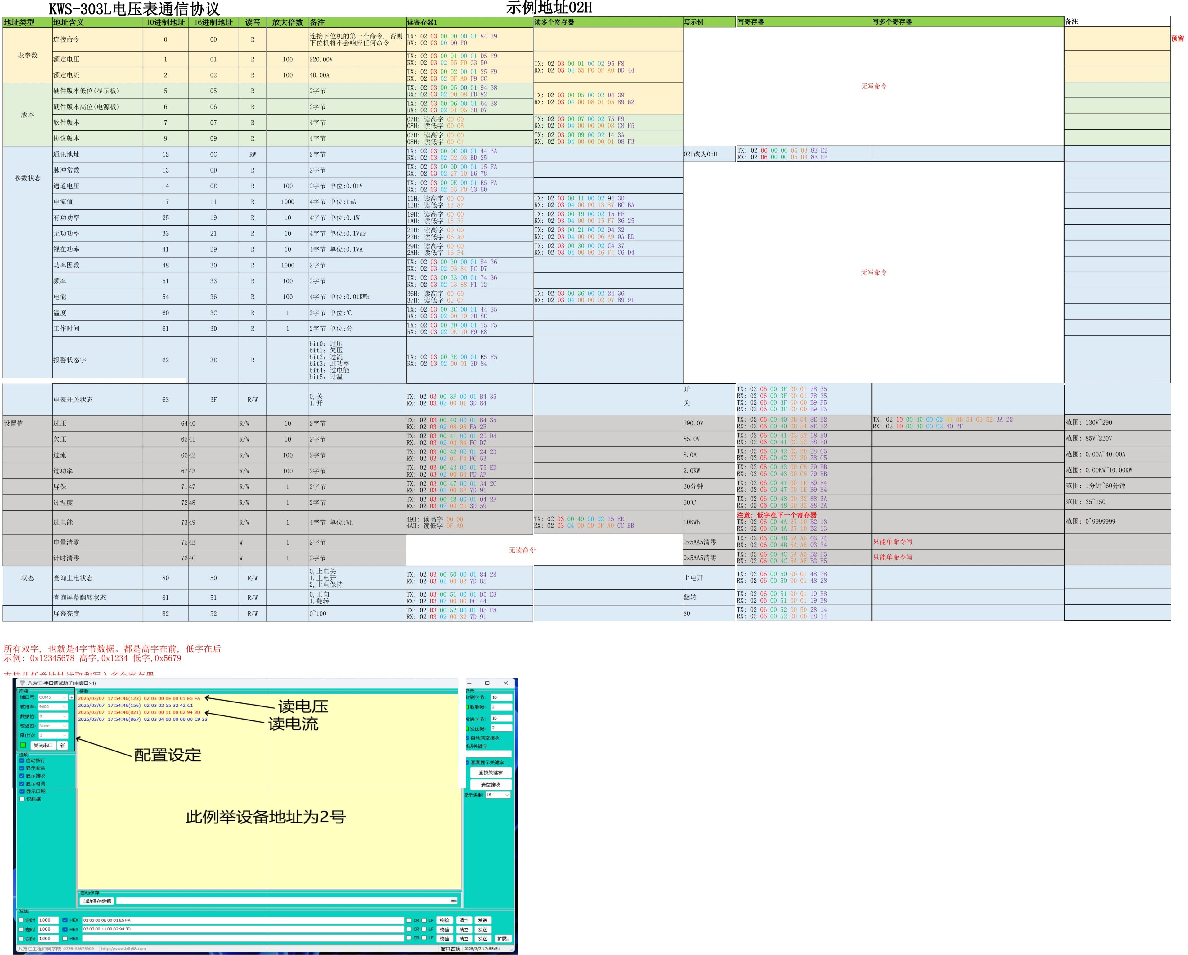
There you can get an Excel file with the Modbus documentation
(unfortunately only in Chinese) which can be displayed.
I have not found a way to download the files.
But you can take screenshots of the Excel file and translate them with Google Translate
and have it translated.
Maybe this will clarify missing registers.
I am still tinkering with it.
Translated with DeepL.com (free version)
Awesome, Frank!
Will update documentation soon with english translation and publish it.
Also I’m preparing my integration for Home Assistant
Added image with chinese protocl description
hello
How is it in your meters? After exceeding the temperature the meter turns off and when the temperature drops it does not turn on? Do you have to turn it on manually?
Hi, Chris
Interesting use-case and haven’t tasted it yet. Will check soon
Hi, Chris
Checked and it doesn’t work. After switching off you have to turn it on manually.
You can use the modbus command to change the relay state to turn the device back on. Obviously you would need to implement this “intelligence” in your application.
Hey, Alexey! Great job! I see there’s home-assistant tag. Did you have any progress with integration to it? I recently purchased couple of such devices for experiments and planning to connect to home assistant with Tasmota running on Wemos D1 mini.